Bitlog is based on Bitmap Logic Simulator. It is a simulator for electronic logic circuits, represented with bitmap images. It is a Turing-complete esoteric visual programming language. Programs can be directly run on this webpage using the "Choose File" button above.
Bitmap Logic Simulator was originally released by "realhet" in 2015. Bitlog was created by Byron Knoll in 2022. While Bitlog is based on the same design as Bitmap Logic Simulator, the programs (i.e. images) for the two projects are not compatible due to implementation differences.
You can email me at byron@byronknoll.com for any questions or comments. The JavaScript code used for running Bitlog programs is open source and released into the public domain.
The background should be pure black (RGB values equal to zero). Any other color is considered a "wire". Any connected wire pixels (up, down, left, and right) will form a single wire. Images can be created using any graphics editor (here is what I use). Use lossless image compression (e.g. PNG) rather than lossy (e.g. JPEG).
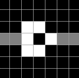
There are five 3x3 pixel combinations which are special: a wire crossing and a NOT gate in each of the four directions.
This is a wire crossing (left connects to right, and top connects to bottom):
This is a NOT gate (input on the left, and output on the right):
Wires have two states: OFF and ON. The ON wires retain their original color, while the OFF wires are dimmed (to 35% of their original RGB values).
Program execution flows in one direction through the NOT gates. When multiple NOT gates are connected together with a wire, this is equivalent to OR logic (if the output of any gate is ON, the wire will become ON).
Wires that are not connected to a NOT output can be clicked on to change their state. If a wire is not connected to any gates, it will always be set to ON (useful for creating text labels).
Cycles (i.e. signal feedback) are allowed. If the cycle length is even, the cycle will be "stable" and not oscillate. If the cycle length is odd, the cycle will be unstable and oscillate. The oscillation can be useful to act as a clock. The speed of the oscillation can be slowed down by chaining together flip-flops (seen in the "clock" example above).
Bitlog execution is deterministic (there are no random numbers). For example, a cycle of length two in a particular image will always have the same ON/OFF configuration (determined by which is visited first based on the position in the image).
For each time step, the state of all wires/gates will be updated. If no changes happen between two time steps, the simulation will stop. The Pause/Resume button can also be used to control the simulation. Changing the state of a wire by clicking on it will also resume the simulation.